Skip to Main Content
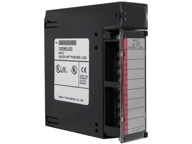
Remanufactured GE-Emerson IC693MDL632 125VDC Positive/Negative Logic Input Module
Provides 8 input points in two isolated group with four points per group.
For on-site repair and support, call us at 1-704-448-2212 or email sales@qualitrol.com.
Part Number
- IC693MDL632RMN
Manufactured
- By GE-Emerson
Overview
Features
- 125VDC rated voltage (Positive or Negative Logic)
- 0 to 150VDC input voltage range
- Isolation:
- 1,500V between field side and logic side
- 500V between groups
- 4.5mA typical input current
- Input characteristics:
- 90 to 150VDC on-state voltage
- 0 to 30VDC off-state voltage
- 3.1mA on-state current
- 1.1mA max. off-state current
- 7ms typical On and Off response time
- Internal power consumption:
- 40mA from the 5V bus on the backplane
- 36mA (typical) from user input supply (all inputs on)
Description
The GE-Emerson IC693MDL632 125VDC Positive/Negative Logic Input Module includes a separate common associated with each group (the two commons are not tied together inside the module. The input module is designed to have either positive logic characteristics in that it sinks current from the input devices to the user common or negative power bus, or negative logic characteristics in that it sources current through the input devices to the user common or positive power bus. The input device is connected between the power bus and the module input. Current into an input point results in a logic 1 in the input status table (%I). Input characteristics are compatible with a wide range of input devices, such as pushbuttons, limit switches, and electronic proximity switches. Power to operate field devices must be supplied by the user.
LED indicators that provide the ON/OFF status of each point are located at the top of the module. This LED block has two horizontal rows with eight green LEDs in each row. This module uses the top row labeled A1 through 8 (points 1 through 8). An insert goes between the inside and outside surface of the hinged door. The surface towards the inside of the module (when the hinged door is closed) has circuit wiring information, and circuit identification information can be recorded on the outside surface. The outside left edge of the insert is color-coded red to indicate a high-voltage module.
This module can be installed in any I/O slot of a 5 or 10-slot baseplate in a Series 90-30 PLC system.
Documents
Need Help? Call an expert at 1-704-702-6380
We're open Mo-Fr 8:00am to 5:00pm