Skip to Main Content
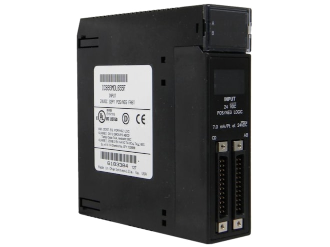
Remanufactured GE-Emerson IC693MDL655 24 Volt DC Positive/Negative Input Module
Provides 32 discrete input points, arranged in four isolated groups of eight, each with its own common.
Remanufactured
$706.00
$635.40
Availability
-
9 in stock
-
Additional 50 ready to ship within 2-3 days
For on-site repair and support, call us at 1-704-448-2212 or email sales@qualitrol.com.
Part Number
- IC693MDL655RMN
Manufactured
- By GE-Emerson
Overview
Features
- 24VDC rated voltage, Positive or Negative Logic
- 0 to 30VDC input voltage range
- Isolation:
- 1,500V between field side and logic side
- 250V between groups
- 7.0mA input current (typical ON current @ 24VDC)
- Input characteristics:
- 11.5 to 30VDC on-state voltage
- 0 to 5VDC off-state voltage
- 3.2mA minimum on-state current
- 1.1mA max. off-state current
- 2ms max. On and Off response time
- Internal power consumption:
- 195mA max. from 5V bus on backplane
- (29mA +0.5mA/point ON +4.7mA/LED ON)
- 224mA typical from isolated 24V bus on backplane or from 24VDC user input supply (all inputs on)
- 195mA max. from 5V bus on backplane
Description
The GE-Emerson IC693MDL655 24 Volt DC Positive/Negative Input Module includes inputs that will operate at levels up to 30V. Backplane isolation between the field side and logic side is provided by opto-couplers on the module. Isolation is also provided between the four groups of inputs on the module, however each group of eight inputs is referenced to the same user common connection. There are no special fault or alarm diagnostics reported. LED indicators (labeled A1 - A8, B1 - B8, C1 - C8, D1 - D8) at the top of the module provide the ON/OFF status of each input point.
The module is configured as a 32-point input type and uses 32 bits of discrete %I input data. Current into an input point results in a logic 1 in the input status table. Power to operate field devices can be supplied by the user, or from the isolated +24 VDC supply available at the module’s I/O connectors. The module can be installed in any I/O slot of a 5 or 10-slot baseplate in a Series 90-30 PLC system.
Connections to the input circuits are made from the user’s input devices to two male (pin-type) 24-pin connectors (Fujitsu FCN-365P024-AU) mounted on the front of the module. The connector mounted on the right of the module (front view) interfaces with groups A and B. The connector on the left side of the module interfaces with groups C and D.
Wiring from the module’s connectors to field devices is made through a cable having a mating female connector on one end and stripped and tinned wires on the other end.
Documents
Need Help? Call an expert at 1-704-702-6380
We're open 8:00 am to 5:00 pm ET