Skip to Main Content
Remanufactured GE-Emerson IC693MDL310 120 Volt and 0.5 Amp AC Output Module
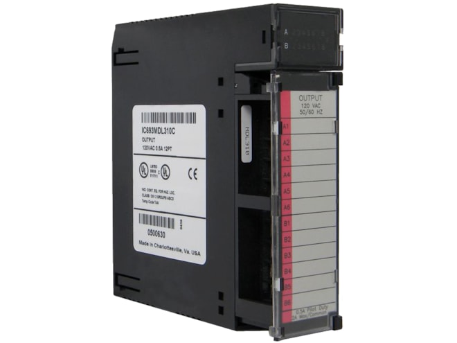
Provides 12 output points in two isolated groups, with six points per group.
For on-site repair and support, call us at 1-704-448-2212 or email sales@qualitrol.com.
Part Number
- IC693MDL310RMN
Manufactured
- By GE-Emerson
Overview
Features
- 120VAC rated voltage
- 85 to 132VAC, 50/60Hz output voltage range
- Isolation:
- 1,500V between field side and logic side
- 500V between each group
- Output current:
- 0.5 Amp max. per point
- 1 Amp max. per group at 140°F
- 2 Amp max. per group at 122°F
- Output characteristics:
- 5 Amps max. inrush current for one cycle
- 50mA minimum load current
- 1.5V max. output voltage drop
- 3mA max. output leakage current at 120VAC
- 1ms max. On response time
- 1/2 cycle max. Off response time
- 210mA power consumption (all outputs on) from 5V bus on backplane
Description
The GE-Emerson IC693MDL310 120 Volt and 0.5 Amp AC Output Module provides a separate common for each of its two groups (the two commons are not tied together inside the module). This allows each group to be used on different phases of the AC supply, or powered from the same supply. Each group is protected with a 3 amp fuse, and an RC snubber is provided for each output to protect against transient electrical noise on the power line. This module provides a high degree of inrush current (10x the rated current) which makes the outputs suitable for controlling a wide range of inductive and incandescent loads. AC Power to operate loads connected to outputs must be user supplied. This module requires an AC power source.
LED indicators that provide the ON/OFF status of each point are at the top of the module. The LEDs are arranged in two horizontal rows with eight green LEDs in each row and a red LED centered between and to the right of the two rows. This module uses the first six LEDs, labeled A1 through 6 in the top row and the first six LEDs, labeled B1 through 6, in the bottom row, for output status. The red LED (labeled F) functions as a blown fuse indicator that turns ON if any of the fuses should blow. An insert goes between the inside and outside surface of the hinged door. The surface towards the inside of the module (when the hinged door is closed) has circuit wiring information, and circuit identification information can be recorded on the outside surface. The outside left edge of the insert is color-coded red to indicate a high-voltage module. This module can be installed in any I/O slot of a 5 or 10-slot baseplate in a Series 90-30 PLC system.
Documents
Need Help? Call an expert at 1-704-702-6380
We're open Mo-Fr 8:00am to 5:00pm