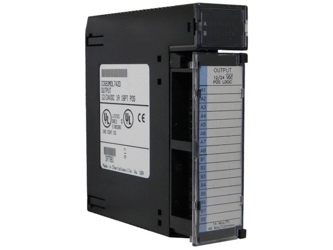
Remanufactured GE-Emerson IC693MDL742 12/24VDC Positive Logic 1A ESCP Output Module
Provides 16 output points in two groups of eight with a common power output terminal for each group.
- IC693MDL742RMN
- By GE-Emerson
Overview
Features
- 12 to 24VDC output voltage range (+20%, -15%)
- Isolation:
- 1,500V between field side and logic side
- 500V between groups
- Output current:
- 1 Amp max. per point
- 4 Amp max. per group at 122°F
- 3 Amp max. per group at 140°C
- Output characteristics:
- 5.2 Amp inrush current for 10ms
- 1.2V max. output voltage drop
- 1mA max. off-state leakage
- 2ms max. On and Off response time
- 130mA power consumption (all outputs on) from 5V bus on backplane
Description
The GE-Emerson IC693MDL742 12/24VDC Positive Logic 1A ESCP Output Module sources current to the loads from the user common or positive power bus. The output device is connected between the negative power bus and the module output. The output characteristics are compatible with a wide range of user-supplied load devices, such as motor starters, solenoids, and indicators. Power to operate the field devices must be supplied by the user.
LED indicators that provide each point's ON/OFF status are located at the top of the module. This LED block has two horizontal rows with eight green LEDs in each row with the top row labeled A1 - A8 (points 1 through 8) and the bottom row labeled B1 - B8 (points 9 through 16). A red LED (labeled “F”) on the right, centered between the two rows of green LEDs, functions as a tripped electronic short circuit protection indicator; it turns ON when any short circuit protection trip occurs. The common signal for each group is monitored electronically. If a short circuit occurs, the output points in the group turn off and the red LED turns on. The LEDs indicating output point status will not turn off. This protection does not protect individual outputs from exceeding their ratings but will protect the board in case of a short-circuited load. To reset electronic short circuit protection remove the 12/24 VDC user supply to the module. The module has two electronic short circuit protection circuits; each protects eight outputs - the first circuit protects A1 - A8, and the second circuit protects B1 - B8.
An insert goes between the inside and outside surfaces of the hinged door. he surface towards the inside of the module (when the hinged door is closed) has circuit wiring information, and circuit identification information can be recorded on the outside surface. The outside left edge of the insert is color-coded blue to indicate a low-voltage module. There are no fuses on the module. The module can be installed in any I/O slot of a 5 or 10-slot baseplate in a Series 90-30 PLC system.
Documents
Need Help? Call an expert at 1-704-702-6380
We're open Mo-Fr 8:00am to 5:00pm