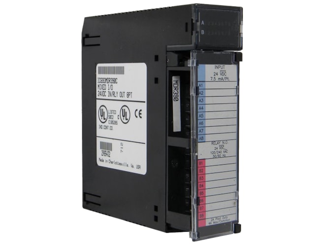
Remanufactured GE-Emerson IC693MDR390 24VDC Input and Relay Output Module
(GE-Fanuc) Provides 8 input points with one common power input terminal and 8 normally-open relay circuits in the same module.
Remanufactured
-
9 in stock
-
Additional 15 ready to ship within 2-3 days
For on-site repair and support, call us at 1-704-448-2212 or email sales@qualitrol.com.
- IC693MDR390RMN
- By GE-Emerson
Overview
Features
- Inputs:
- -30 to +32VDC input voltage range
- Isolation:
- 1,500V RMS between field and logic side
- 500V RMS between inputs
- 7.5mA typical input current at rated voltage
- Input characteristics:
- 15 to 32VDC on-state voltage
- 0 to 5VDC off-state voltage
- 4mA minimum on-state current
- 1.5mA max. off-state current
- 7ms typical On and Off response time
- Outputs:
- Operating voltage:
- 5 to 30VDC
- 5 to 250VAC, 50/60Hz
- Isolation:
- 1,500V RMS between field and logic side
- 500V RMS between groups
- Maximum load:
- 2 Amps max. per output
- 4 Amps max. per common
- 10mA minimum load
- 5 Amps max. inrush
- 15ms max. On and Off response time
- Internal power consumption:
- 80mA (all I/O on) from 5V backplane bus
- 70mA (all outputs on) from relay 24V backplane bus
- Operating voltage:
Description
The GE-Emerson (GE-Fanuc) IC693MDR390 24VDC Input and Relay Output Module either sinks or sources current to/from the input devices to/from the user common and is arranged as one group of eight inputs. The relay output circuits are arranged in two groups of four circuits each. Each group has a common power output terminal.
Input characteristics are compatible with a wide range of user-supplied devices, such as pushbuttons, limit switches, and electronic proximity switches. Current through an input results in a logic 1 in the input status table (%I). Power to operate the field devices must be supplied by the user.
The normally-open relay circuits are used for controlling output loads provided by the user. The output switching capacity of each output is 2 amps. The relay outputs can control a wide range of user-supplied load devices, such as motor starters, solenoids, and indicators. Power for the internal relay circuits is provided by the +24 volt DC bus on the backplane. The user must supply the AC or DC power to operate field devices. There are no fuses on this module.
LED indicators that provide each point's ON/OFF status are located at the top of the module. The LEDs are arranged in two horizontal rows with eight green LEDs in each row. The top row is labeled A1 through 8 (input points 1 through 8) and the bottom row is labeled B1 through B8 (relay output points 1 through 8). An insert goes between the inside and outside surfaces of the hinged door. The surface towards the inside of the module (when the hinged door is closed) has circuit wiring information, and circuit identification information can be recorded on the outside surface. The top half of the outside left edge of the insert is color-coded blue to indicate low-voltage circuits and the bottom half of the outside left edge is color-coded red to indicate high-voltage circuits.
The module can be installed in any I/O slot of a 5 or 10-slot baseplate in a Series 90-30 PLC system.
Need Help? Call an expert at 1-704-702-6380
We're open Mo-Fr 8:00am to 5:00pm