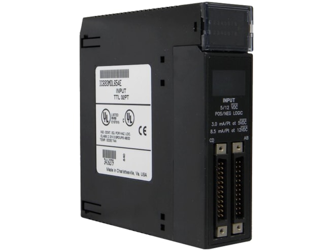
Repair GE-Emerson IC693MDL654 5-12V TTL Positive/Negative Logic Input Module
(GE-Fanuc) Provides 32 discrete TTL voltage threshold input points.
Remanufactured
-
32 in stock
-
Additional 55 ready to ship within 2-3 days
For on-site repair and support, call us at 1-704-448-2212 or email sales@qualitrol.com.
- IC693MDL654REP
- By GE-Emerson
Overview
Features
- 5 to 12VDC rated voltage, Positive or Negative Logic
- 0 to 15VDC input voltage range
- Isolation:
- 1,500V between field side and logic side
- 250V between groups
- Input current:
- 3.0mA (typical ON current @ 5VDC)
- 8.5mA (typical ON current @ 12VDC)
- Input characteristics:
- 4.2 to 15VDC on-state voltage
- 0 to 2.6VDC off-state voltage
- 2.5mA minimum on-state current
- 1.2mA max. off-state current
- 1ms max. On and Off response time
- Internal power consumption:
- 195mA max. from 5V bus on backplane
- 96mA typical from user input supply @ 5VDC and all inputs on
- 272mA typical from user input supply @ 12VDC and all inputs on
- +5 volts DC ±5% isolated 5V supply
- 150mA typical current limit
Description
The GE-Emerson (GE-Fanuc) IC693MDL654 5-12V TTL Positive/Negative Logic Input Module includes inputs arranged in four isolated groups of eight (A1 - A8, B1 - B8, C1 - C8, and D1 - D8). Each group has its own common. The inputs are positive or negative logic inputs and will operate at levels up to 15V.
A single, regulated +5V supply (current limited to approximately 150 mA) is available through the I/O connectors on the front of the module. This supply is generated on the module and is isolated from the backplane. Its power input comes from the +5V logic supply on the PLC backplane. By installing jumpers on the appropriate pins on the I/O connector, you can choose to power the inputs from this internal supply instead of powering them with an external user-provided supply. If this internal supply is used to power the inputs, additional loading will be placed on the PLC’s +5V power supply. Backplane isolation between the field side and logic side is provided by opto-couplers on the module. There are no special fault or alarm diagnostics reported. LED indicators (labeled A1 - A8, B1 - B8, C1 - C8, D1 - D8) at the top of the module provide the ON/OFF status of each input point.
The module is configured as a 32-point input type and uses 32 bits of discrete %I input data. Current into an input point results in a logic 1 in the input status table. This module can be installed in any I/O slot of a 5 or 10-slot baseplate in a Series 90-30 PLC system.
Connections to the input circuits are made from the user’s input devices to two male (pin-type) 24-pin connectors (Fujitsu FCN-365P024-AU) mounted on the front of the module. The connector mounted on the right of the module (front view) interfaces with groups A and B. The connector on the left side of the module interfaces with groups C and D.
Wiring from the module’s connectors to field devices is made through a cable having a mating female connector on one end and stripped and tinned wires on the other end.
Documents
Need Help? Call an expert at 1-704-702-6380
We're open 8:00 am to 5:00 pm ET