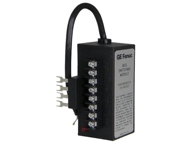
Remanufactured GE-Emerson IC660BSM021 Genius Bus Switching Module
24/48VDC, connects Genius I/O blocks to dual communications cables.
Remanufactured
-
5 in stock
-
Additional 7 ready to ship within 2-3 days
For on-site repair and support, call us at 1-704-448-2212 or email sales@qualitrol.com.
- IC660BSM021RMN
- By GE-Emerson
Overview
Features
- 32 to 140°F operating temperature
- -40 to 158°F storage temperature
- 5 to 95% humidity (non-condensing)
- 3.5in (H) x 2.25in (W) x 2.5in (D)
- Input voltage:
- Bus B selected: 18 to 56VDC (not polarized)
- Bus A selected: less than 4VDC (not polarized)
- Current draw:
- At 24VDC: 17mA max., 10mA min.
- At 48VDC: 60mA max., 30mA min.
- 500,000 operations min. reliability
- Less than 20ms switch activation time (including switch bounce)
- Less than 70ms switch release time (including switch bounce)
Description
The GE-Emerson IC660BSM021 Genius Bus Switching Module is used to connect I/O devices to two serial buses at the same time.
One BSM can connect up to eight discrete and analog blocks to a dual bus. Using additional BSMs permits up to 30 I/O blocks to interface to the same dual bus.
This dual bus configuration can be used to provide a backup communications path to be used in case of bus failure.
Each bus of a dual bus pair is connected to a bus interface module (Bus Controller or PCIM). If each bus interface module resides in a different CPU, the system can also support CPU redundancy.
A phase B discrete block in the cluster controls the operation of the Bus Switching Module. The first circuit on this discrete block functions as an output dedicated to the BSM. This output causes the BSM to switch busses if communications are lost on the cur- rent bus.
If an operational bus cannot be found with one switch of the BSM, the BSM waits until communication is restored on the connected bus, or until power is cycled to the BSM controller block. This prevents unnecessary switching by the BSM when no communications are present. De-energized, the BSM connects the block(s) to bus A. The BSM is energized only when selection of bus B is required.
The LED on the Bus Switching Module lights when bus B is active.
The BSM can also be commanded to switch busses by the CPU or Hand-held Monitor.
Need Help? Call an expert at 1-704-702-6380
We're open Mo-Fr 8:00am to 5:00pm