Skip to Main Content
Remanufactured GE-Emerson IC693MDL748 24/48VDC Positive Logic 0.5 Amp Output Module
Provides 8 output points in one group with a common power input terminal.
Remanufactured
$645.35
Availability
-
Additional 33 ready to ship within 2-3 days
For on-site repair and support, call us at 1-704-448-2212 or email sales@qualitrol.com.
Part Number
- IC693MDL748RMN
Manufactured
- By GE-Emerson
Overview
Features
- 24 to 48VDC output voltage range (+/- 25%)
- 1,500V isolation between field side and logic side
- 0.5 Amp output current max. per point
- Output characteristics:
- 9.4 Amp inrush current for 10ms
- 1.2V max. output voltage drop
- 1mA max. off-state leakage
- 2ms max. On and Off response time
- 60mA power consumption (all outputs on) from 5V bus on backplane
Description
The GE-Emerson IC693MDL748 24/48VDC Positive Logic 0.5 Amp Output Module sources current to the output devices from the user positive power bus. Output devices are connected between the negative power bus and the module outputs. The output characteristics are compatible with a wide range of user-supplied output devices, such as motor starters, solenoids, and indicators. Power to operate output devices must come from an external power source supplied by the user. This module is rated for either 24 or 48VDC positive logic 0.5 Amp output applications.
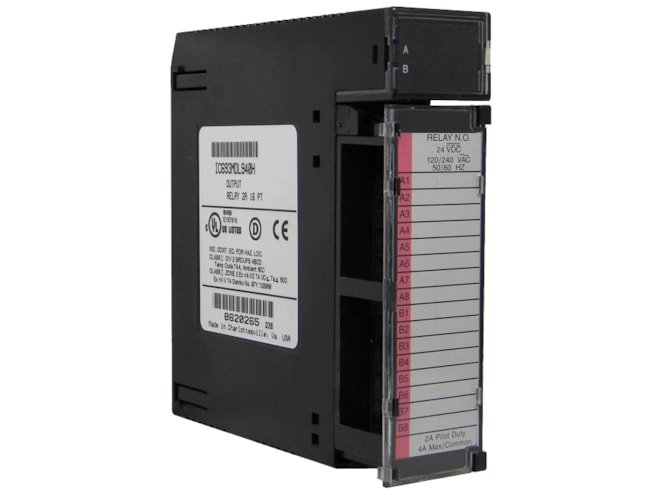
LED indicators that provide each point's ON/OFF status are located at the top of the module. LEDs are arranged in two horizontal rows with eight green LEDs in each row. This module uses only the top row labeled A1 through 8 (points 1 through 8). The bottom row of LEDs (labeled “B”) is not used on this module. A red LED (labeled “F”) on the right and centered between the two rows of green LEDs functions as a blown fuse indicator; it turns ON when either fuse is blown. The module has two 3.15 Amp fuses, with each fuse protecting four outputs; the first fuse protects outputs A1 – A4, and the second fuse protects outputs A5 – A8. These fuses are connected to the same positive supply connection (see Figure 1). An insert fits between the inside and outside surface of the module’s hinged cover. The back of the insert has circuit-wiring information, and circuit identification information can be written on the front of the insert. The front left edge of the insert is color-coded blue to indicate a DC-type module.
This module can be installed in any I/O slot of a 5 or 10-slot baseplate in an IC693-Series PLC system.
Documents
Need Help? Call an expert at 1-704-702-6380
We're open 8:00 am to 5:00 pm ET