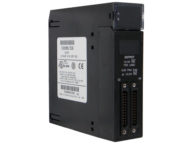
Remanufactured GE-Emerson IC693MDL753 12/24VDC Positive Logic 0.5 Amp Output Module
(GE-Fanuc) Provides 32 discrete outputs arranged in four isolated groups of eight (A1 - A8, B1 - B8, C1 - C8, and D1 - D8).
Remanufactured
-
4 in stock
-
Additional 70 ready to ship within 2-3 days
For on-site repair and support, call us at 1-704-448-2212 or email sales@qualitrol.com.
- IC693MDL753RMN
- By GE-Emerson
Overview
Features
- 10.2 to 28.8VDC output voltage range
- Isolation:
- 1,500V between field side and logic side
- 250V between groups
- Output current:
- 0.5 Amp per point with 4 Amp max. per group
- 3 Amp max. per group common pin
- Output characteristics:
- 5.4 Amp inrush current for 10ms
- 0.3VDC on-state voltage drop
- 0.1mA max. off-state leakage current
- 0.5ms max. On and Off response time
- Internal power consumption:
- 260mA max. from 5V bus on backplane (13mA + 3mA/point ON + 4.7mA/LED)
- 16.5mA max. per group from user supply at 24VDC and all eight outputs in group ON
- 9.6mA max. per group from user supply at 12VDC and all eight outputs in group ON
Description
The GE-Emerson (GE-Fanuc) IC693MDL753 12/24VDC Positive Logic 0.5 Amp Output Module switches the loads on the positive side of the power supply, and therefore supply current to the load.
The outputs can switch user loads over the range of +12 through +24 VDC (+20%, –15%) and are capable of sourcing a maximum current of 0.5 amps per point. Two pins are provided on the user I/O connectors for each group common. Each pin has a current handling capability of 3 amperes. It is recommended that connections are made to both pins when connecting the common; however, it is a requirement for high current applications (between 3 and 4 amperes).
Each group can be used to drive different loads. For example, groups A, B, and C can drive 24 VDC loads, while group D can be reserved for driving 12 VDC loads. Power to provide current to the loads must be provided by the user. The module also draws a minimum amount of power from the user supply to provide gate drive to the output devices.
Backplane isolation between the field side and logic side is provided by optocouplers on the module.
All 32 outputs are forced OFF when the CPU is stopped. There are no special fault or alarm diagnostics reported. LED indicators (labeled A1 - A8, B1 - B8, C1 - C8, D1 - D8) at the top of the module provide the ON/OFF status of each output point.
This module is configured as a 32-point output type and uses 32 bits of discrete %Q output data. This module can be installed in any I/O slot of a 5 or 10-slot baseplate in a Series 90-30 PLC system.
Connections from the output circuits are made to the user load devices from two male (pin-type) 24-pin connectors (Fujitsu FCN-365P024-AU) mounted on the front of the module. The connector mounted on the right of the module (front view) interfaces with groups A and B. The connector on the left side of the module interfaces with groups C and D.
Documents
Need Help? Call an expert at 1-704-702-6380
We're open Mo-Fr 8:00am to 5:00pm